Very large scale integration (vlsi): 4-bit synchronous “up” counter Design a 3-bit synchronous binary counter What is synchronous counter? definition, circuit and operation of
Digital Electronics Laboratory
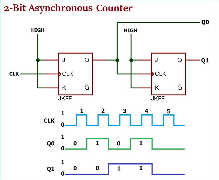
Asynchronous up counter circuit diagram 16. the 4 bit synchronous up counter circuit constructed with t 4 bit asynchronous up counter
3 bit synchronous down counter
Synchronous counter : types and its applicationsSynchronous counters binary clock counting sequence asynchronous circuit flops sequential pulse examine electronics Mod 12 counter circuit diagramCounter bit synchronous circuit scale four integration vlsi very large.
Synchronous counter in digital electronics with circuit diagramAsynchronous ripple geeksforgeeks Counter bit synchronous binary 3bit digital which3 bit asynchronous up counter(हिन्दी ).

Asynchronous counter: definition, working, truth table & design
Counter synchronous flip bit binary using flops diagram circuit parallel flipflop here gatesDigital logic Synchronous counters flops sequential asynchronous circuitsSynchronous timing asynchronous counters logic 4bit geeksforgeeks.
Unit 5: countersDigital up down counter circuit diagram Digital electronics laboratoryUp counter circuit diagram.

Differences between synchronous and asynchronous counter
Counter bit asynchronousDesign asynchronous up/down counter Counter flip synchronous flop jk gates output inputSynchronous counters flop flops clocked sequential inputs.
Asynchronous decade counter circuit diagramSynchronous flop geeksforgeeks toggle Design a 3-bit gray code counter using jk flip flopsAsynchronous synchronous timing geeksforgeeks.

Virtual labs
Synchronous counter diagramSynchronous counters Counter asynchronous circuit electronics count flip using clock digital flops state bits board tutorialSynchronous counters.
Design asynchronous up/down counterAsynchronous up counter circuit diagram Counter synchronous bcd flip mod10 flops constructed murat fig1917. the bcd (mod10) synchronous up counter circuit constructed with d.

Synchronous up counter circuit diagram
Synchronous counterSynchronous flop flops Synchronous countersDesign a 3 bit binary counter using d flip-flops.
Synchronous counter and the 4-bit synchronous counter4 bit synchronous counter circuit diagram 4 bit counter truth tableCounter counters asynchronous decade logic digital flip flop circuit bits pgt state diagram timing flops clock realisation electronics counting here.


Synchronous Counter and the 4-bit Synchronous Counter

synchronous counter diagram - Wiring Diagram and Schematics

3 bit Synchronous Down Counter - GeeksforGeeks
Asynchronous Counter: Definition, Working, Truth Table & Design

Digital Electronics Laboratory

Mod 12 Counter Circuit Diagram

Up Counter Circuit Diagram
